|
Creating Curves or Framework
Curves are spline line segments controlled by CVs. Curves are the framework of shapes. CVs (or control vertices) are the points which control and make up the line curve. These lines are called NURBS (non-uniform rational b-splines). NURBS are special because they form smooth curves between CVs.
Select the Modeling section of Maya, hit F3 button on the keyboard, or choose from upper left, status line.
Choose Create->CV Curve Tool->
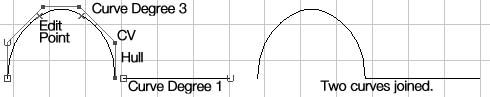
Click on Curve Degree 3 for rounded curves, use 1 for straight curves.
Click on Close
Click the mouse to input CVs in any view to create a curve.
Hit Enter button on the keyboard when you are finished.
Choose Edit Curves->Open/Close Curves (This will close an active curve.)
Combining straight and rounded curves
Select the Modeling section of Maya, hit F3 button on the keyboard, or choose from upper left, status line.
To draw the example below:
Choose Create->CV Curve Tool->
Click on Curve Degree 3 to draw the the rounded curve
Hit the Return button on the keyboard to finish the curve.
Choose Create->CV Curve Tool->
Click on Curve Degree 1 to draw the straight curve
Hit the Return button on the keyboard to finish the curve.
Use Edit Curves->Attach Curves-> Curve to join the two curves.
Choose Attach Method Connect
Uncheck Keep Originals
Click Attach
Use Edit->Delete by Type->History to delete the construction history,
Grid Snap Option
This option snaps CVs and object pivot points to nearest grid location while inputting or transforming. This is useful when precision is required.
The Grid Snap button from the Status Line.  Keyboard shortcut: Hold down x while transforming an object or CV. Keyboard shortcut: Hold down x while transforming an object or CV.
Point Snap, Lock CVs to existing CVs.
This option snaps CVs and object pivot points to existing CVs or edit points.
Select the object to snap to.
Use Display->Nurbs Components->CVs, this will make the CVs visible on active objects.
The Point Snap button from the Status Line. 
Keyboard shortcut: Hold down v while transforming an object or CV
Curve Snap
Curve Snap allows you to move a objects, pivots or points along a curve.
The curve Snap button from the Status Line.  Keyboard shortcut: hold down c while transforming an object or CV. Keyboard shortcut: hold down c while transforming an object or CV.
Add CVs to Existing Surface
This function allows you to input a row of CVs in-between existing isoparms on 3D surfaces.
In object type  mode, select the Nurbs surface you would like to add a row of CVs to. mode, select the Nurbs surface you would like to add a row of CVs to.
Move the mouse over the object, hold down the right mouse button to bring up the object menu, select isoparm. Click and drag on one of the existing isoparms to copy it and move it over the surface of the object.
Select Edit Nurbs->Insert Isoparms. Hold down shift to select more than one.
Detach
This function allows you to cut a surface along an isoparam.
It also will break a curve at an edit point.
In object type mode, select the Nurbs surface you would like to detach.
Move the mouse over the object, hold down the right mouse button to bring up the object menu, select isoparm, Click on one of the isoparms to select it.
Select Edit Nurbs->Detach Surfaces
Templates
This function allows you to turn an active object into a template. Objects that are inactive templates can not be manipulated as an object. If you attempt to pick a template with the selection tool the template will not highlight. The template color is gray.
Pick all objects to turn into templates.
Choose Display->Object Components->Templates
or hold down the right mouse button over active objects, this brings up the object menu, select Actions->Template.
*** To turn your template back into an object:
In hierarchy  mode, choose the template button mode, choose the template button  which is usually off by default. which is usually off by default.
Select the template you would like to come back to life.
Choose Display->Object Components->Templates
or hold down the right mouse button over active templates, this brings up the object menu,
select Actions->Template.
Invisible
This function allows you to make an active object invisible. This will alleviate the data-base load because there will be fewer items to draw, this makes your screen draw faster.
Pick all objects to turn invisible.
Choose Display->Hide->Hide Selection (The object(s) will disappear.)
***To turn your object visible:
Choose Display->Show->All
Adjust the Tension of a CV.
Hardness effects the tension or change in tightness of a curve.
Pick the component type button in the status line near the top.
The CVs will automatically appear. This lets you pick CVs, rather than objects etc.
Pick 1 CV
Select Edit Curves->CV Hardness
This Creates sharp corners at the active CVs. There are some limitations.
Give a Curve a Surface.
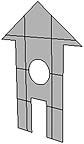
Curves are framework, which means they have no surface. Use Planar to surface flat curves. The closed curves will trim out regions on a primitive plane to create the surface.
Draw some curves, place one inside of the other.
Use Curves->CV Curve Tool->
Click on Curve Degree 1 for straight lines, use Degree 3 for rounded lines.
Click on Close
Hit Enter when you are finished.
Choose Edit Curves->Open/Close Curves (Close the active curves.)
Select all of the curves, choose Surfaces->Planar.
Revolve
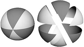
Revolve will lathe a cross-section around the X,Y, or Z axes, a certain number of degrees.
Input a profile curve in the front view up against the axis. (Later you may use any view.)
Pick the curve.
Choose Surfaces->Revolve->
Select Axis Preset Y
Select End Sweep Angle 360 (Number of degrees curve will sweep around.)
Select Segments 6 (Number of times the curve will be placed during the sweep.)
Click on Revolve
Revolve Examples
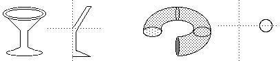
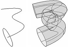
Extruded Surfaces with a Curve Path
This tool will sweep a curve along a path.
Draw a curve to be used as a cross-section.
Draw a path.
Orient the cross-section centered and perpendicular to the path, use translate and rotate.
Select the cross-section and then the path
Select Surfaces->Extrude->
Choose Style Tube
Choose Result Position At Path
Choose Pivot Closest End Point
Choose Orientation Profile Normal
Choose Curve Range Complete
Choose Output Geometry NURBS
Try out the various options, compare the differences.
Extruded Surfaces with a Profile, Using Distance
Draw a curve in the any view, for now use the front view.
Select the curve.
Select Surfaces->Extrude->
Choose Style Distance
Input a length
Choose Direction Specify
Choose the Z Axis
Click Extrude

Duplicate Existing Curves
This function lets you make an exact duplicate of an isoparm from a surface.
In object type mode, select the Nurbs surface you would like to duplicate a curve from.
Move the mouse over the object, hold down the right mouse button to bring up the object menu, select isoparm. Click on one of the isoparms to select it.
Use Edit Curves->Duplicate Curves to make a new curve from the active isoparm.
Connect Cross-sections with Loft
In the front view draw two or more curve cross-sections. (This will work in any view.)
Place the cross-sections in different positions along the z axis. (This works with any axis.)
Hold down the Shift key and select all the curves in order.
Use Surfaces->Loft (This will connect the cross-sections.)
Attribute Editor
The attribute editor allows you to name, transform, adjust color, change subdivisions, or see information about objects, CVs, lights, or the camera.
Pick an object.
Window->Attribute Editor...
Some of the options:
Name: Change the name of an object by clicking on the box next to the name box. Type a new name.
Transform Attributes:
translate: Enter x,y,z positions.
rotate: Enter x,y,z rotations.
scale: Enter x,y,z scales.
Pivots:
Rotate Pivot: Look at x,y,z rotate pivot positions.
Local Axes: Look at x,y,z scale pivot positions.
Scale Pivot: Look at x,y,z scale pivot positions.
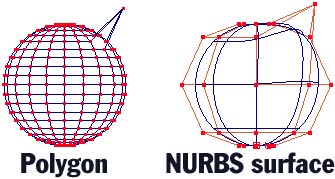
Polygon Mesh versus NURBS Surface
|
Poly Mesh
Each point is connected by a straight line. Many points are needed to make a smooth curve.
No need to bother with rows of CVs. |
|
|
NURBS Surface
Points are connected by curved splines. A few points can define a smooth curve.
It is easy to create smooth curved surfaces.
Can adjust the subdivisions to make the surface more round.
Can be converted into a polygon mesh. |
|
Poly Mesh
A polygon mesh object is made of polygons. The illustration above indicates the 4 polygons that make up the cube. A polygon is a closed planer surface. The smoothness of an object depends on the number of polygons defined.
A list of data points for the polygon mesh above may appear as follows:
List of vertices and their number.
1) -1, 1, 0
2) -1, 0, 0
3) 0, 0, 0
4) 0, 1, 0
5) 0, 0, 1
6) 0, 1, 1
7) -1, 0, 0
8) -1, 1, 0
List of polygons and the vertices that construct them.
1) 1, 2, 3, 4
2) 1, 2, 7, 8
3) 8, 7, 5, 6
4) 5, 6, 4, 3
NURBS Surface
A NURBS surface is made of parametric cubic curves. In other words, edges are connected to form a continuous grid like surface.
A list of data points for a patch may appear as follows:
List of vertices and their edge number.
|
|
-1, 0 0
-1, 1, 0
0, 0, -1
0, 1, -1
1, 0, 0
1, 1, 0
2, 0, -1
2, 1, -1 |
|
|