Sets of faces
With the same rational we can construct more than one face and draw them simultaneously. In the source code below we modified the previous MyFace class to accommodate two faces that we put into an array called face[]. First we create a face out of the points array and then we create another face with the same array and move it 100. in the z direction.
import
java.applet.*;
import
java.awt.*;
import
java.awt.image.*;
public
class MyFace extends Applet{
MyPoint[] points;
MyFace[] face;
int numFaces;
int xf, yf;
//**********************
public
void init(){
points = new MyPoint[4];
points[0] = new MyPoint(0.,0.,0.);
points[1] = new MyPoint(100.,0.,0.);
points[2] = new MyPoint(100.,100.,0.);
points[3] = new MyPoint(0.,100.,0.);
numFaces = 2;
face = new MyFace[numFaces];
face[0] = new MyFace(points);
face[1] = new MyFace(points);
face[1].move(0., 0., 100.);
for(int i=0; i<numFaces; i++)
face[i].move(-50., -50.,-50.);
}
/**
*******************/
public void paint(Graphics g){
for(int i=0; i<numFaces; i++)
face[i].draw(g);
}
//************************************************
public boolean mouseDown(Event e, int x,
int y){
xf = x;
yf = y;
return true;
}
//************************************************
public boolean mouseDrag(Event e, int x,
int y){
int xoff = x - xf;
int yoff = y - yf;
for(int i=0; i<numFaces; i++)
face[i].rotatey(xoff*Math.PI/180);
for(int i=0; i<numFaces; i++)
face[i].rotatex(yoff*Math.PI/180);
repaint();
xf = x;
yf = y;
return true;
}
}
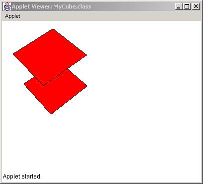
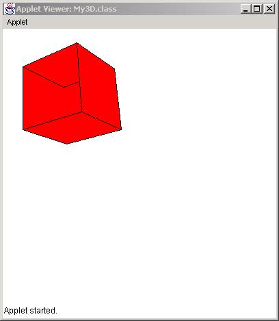
The result is:
Class MySolid
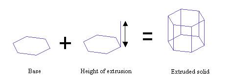
From the previous example, it becomes apparent that we can create as many faces we want by populating the face[] array with more faces. However, certain arrangements of faces may form known solid objects, such as a cube, a pyramid, or a sphere. In this case we can construct a new class, called MySolid, in which we will create arrangement of faces that will form known solids. Let start with a general formation of solids called extrusion. In extrusion, we construct solids out of a base polygon and a height of extrusion as shown below:
So for an extruded solid class, the constructor should be a set of points that form the base and a height. The following code shows how an extruded soild can be created (out of many other ways):
import
java.awt.*;
public
class MySolid {
MyFace[] faces;
int numFaces;
//*********************** Constructor
**********
public MySolid(MyPoint[] inPoints, double
height){
numFaces
= 0;
faces = new MyFace[inPoints.length
+ 2];
//bottom
faces[0] = new MyFace(inPoints);
numFaces++;
//top
faces[1] = new MyFace(inPoints);
faces[1].setMove(0., 0., height);
numFaces++;
// side faces - 1
MyPoint[] side;
side = new MyPoint[4];
for(int i=0;
i<inPoints.length-1; i++){
side[0] = new MyPoint(faces[0].points[i].x,
faces[0].points[i].y,
faces[0].points[i].z );
side[1] = new MyPoint(faces[0].points[i+1].x,
faces[0].points[i+1].y,
faces[0].points[i+1].z );
side[2] = new MyPoint(faces[1].points[i+1].x,
faces[1].points[i+1].y,
faces[1].points[i+1].z
);
side[3] = new MyPoint(faces[1].points[i].x,
faces[1].points[i].y,
faces[1].points[i].z );
faces[numFaces] = new MyFace(side);
numFaces++;
}
//
last side face
int
last = inPoints.length-1;
side[0] = new
MyPoint(faces[0].points[last].x,
faces[0].points[last].y,
faces[0].points[last].z );
side[1] = new
MyPoint(faces[0].points[0].x,
faces[0].points[0].y,
faces[0].points[0].z );
side[2] = new
MyPoint(faces[1].points[0].x,
faces[1].points[0].y,
faces[1].points[0].z );
side[3] = new MyPoint(faces[1].points[last].x,
faces[1].points[last].y,
faces[1].points[last].z );
faces[numFaces] = new MyFace(side);
numFaces++;
}
//******************
public void draw(Graphics g){
for(int i=0; i<numFaces; i++)
faces[i].draw(g);
}
//*************
public void setRotatex (double angle) {
for(int i=0; i<numFaces; i++)
faces[i].setRotatex(angle);
}
//*************
public void setRotatey (double angle) {
for(int i=0; i<numFaces; i++)
faces[i].setRotatey(angle);
}
//*************
public void setRotatez (double angle) {
for(int i=0; i<numFaces; i++)
faces[i].setRotatez(angle);
}
//*************
public void setScale(double xs, double ys, double zs){
for(int i=0; i<numFaces; i++)
faces[i].setScale(xs, ys, zs);
}
//*************
public void setMove(double xoff, double yoff, double zoff){
for(int i=0; i<numFaces; i++)
faces[i].setMove(xoff, yoff, zoff);
}
}
Lets take a closer look at the constructor. The class MySolid has two data members:
MyFace[]
faces;
int numFaces;
A set of points (that form the base) and the number of faces (numFaces). The constructor takes two arguments, a set of input points (inPoints) and the height of extrusion. The first thing we do is to allocate memory for the faces. That is easy, because we know in advance how many faces we will need, that is, the number of points of the base plus 2. Ant extruded object has a bottom and a top face and then as side faces, as many as the number of points.
faces = new MyFace[inPoints.length
+ 2];
Then we create the bottom face which is formed by whatever points are in the input base:
faces[0]
= new MyFace(inPoints);
Then do the same thing for the top except we move it by height units in the z-direction:
faces[1]
= new MyFace(inPoints);
faces[1].setMove(0., 0., height);
We also increment the numFaces as we add more faces:
numFaces++;
Finally we need to construct the side faces. Thus, we loop for the number of incoming point –1 and for each loop we collect a) the current point of the bottom face, b) the next point of the bottom face, c) the next point of the top face, and d) the current point of the top face. These four points we put in a MyPoint[] array, which we use to construct the side face.
MyPoint[] side;
side = new MyPoint[4];
for(int i=0; i<inPoints.length-1;
i++){
side[0] = new MyPoint(faces[0].points[i].x,
faces[0].points[i].y,
faces[0].points[i].z );
side[1] = new MyPoint(faces[0].points[i+1].x,
faces[0].points[i+1].y,
faces[0].points[i+1].z );
side[2] = new MyPoint(faces[1].points[i+1].x,
faces[1].points[i+1].y,
faces[1].points[i+1].z
);
side[3] = new MyPoint(faces[1].points[i].x,
faces[1].points[i].y,
faces[1].points[i].z );
faces[numFaces] = new MyFace(side);
numFaces++;
}
The figure below illustrates the position of the points and faces for a hexagon:
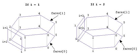
These loops take care of the inPoints.length-1 sides, that is n–1, where n is the number of points. We cannot construct the last face because i+1 will take us out of the boundaries of the array when i = inPoints.length. So we construct the n-1 side faces and when done, we construct the last side face, which is:
// last side face
int last = inPoints.length-1;
side[0] = new MyPoint( faces[0].points[last].x,
faces[0].points[last].y,
faces[0].points[last].z );
side[1] = new MyPoint( faces[0].points[0].x,
faces[0].points[0].y,
faces[0].points[0].z );
side[2] = new MyPoint( faces[1].points[0].x,
faces[1].points[0].y,
faces[1].points[0].z );
side[3] = new MyPoint( faces[1].points[last].x,
faces[1].points[last].y,
faces[1].points[last].z );
faces[numFaces] = new MyFace(side);
numFaces++;
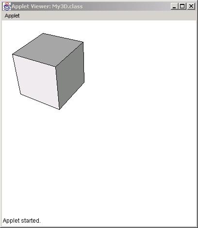
The result is:
You may notice that the faces do not appear in the right order. In fact, when paint() draws the faces, it fills a polygon in the order 0, 1, 2, 3, 4,5, etc. But faces[0] is the bottom, faces[1] is the top and the rest are side faces. This not the order they should have to paint them from the most far to the most close. The solution to this problem is to either paint them in the right order or find a way to omit the faces that are hidden, that is, the faces in the back.
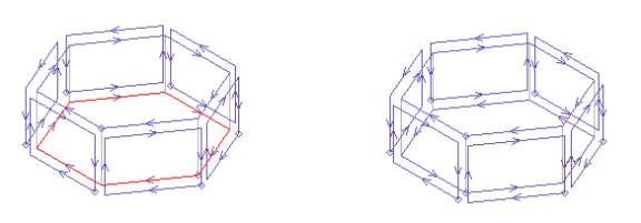
Face Visibility
Suppose we have a cube in 3D. The cube is composed of six faces. Each face was constructed in a clockwise fashion. However the projection of each face is not all clockwise. It seems that the faces that are in the back of the object are counter-clockwise. These faces are shown here in red.
If we choose not to display these faces we end up with only the faces that are visible:
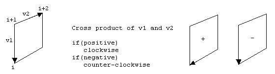
The algorithm for determine whether a 2D polygon is clockwise or counterclockwise is based on simple algorithm that uses the cross product of vectors. The method belongs to the MyFace class and is shown here (cross products are covered in the following sections):
/********************************************
Determines whether a set of point in a polygon
is clock or counter-clockwise
This routine is useful for telling whether a face is visible
*******************************************/
public boolean visible(Polygon poly) {
float x1, y1, x2, y2, norm=0;
int ahead1, ahead2;
for (int i=0; i<poly.npoints; i++) {
ahead1 = i+1;
ahead2 = i+2;
if(i == (poly.npoints-2)) ahead2 = 0;
if(i == (poly.npoints-1)) { ahead2=1; ahead1=0; }
x1 = poly.xpoints[i] - poly.xpoints[ahead1];
y1 = poly.ypoints[i] - poly.ypoints[ahead1];
x2 = poly.xpoints[ahead2] - poly.xpoints[ahead1];
y2 = poly.ypoints[ahead2] - poly.ypoints[ahead1];
norm += (x1*y2 - y1*x2);
}
if(norm > 0.0) return false;
else return true;
}
In the above code, we take each point of the polygon and we construct two vectors: the previous and the next one. Then we take their cross product. If the value is positive we have a clockwise sequence. Otherwise we have a counter-clockwise sequence.
 This
method is then used in the draw() method in the following way:
This
method is then used in the draw() method in the following way:
//******************
public void draw(Graphics g){
Polygon poly = new Polygon();
for(int i=0; i<numPoints; i++){
MyPoint p = points[i].setPerspective();
poly.addPoint((int)p.x+100, (int)p.y+100);
}
if(visible(poly)){
g.setColor(color);
g.fillPolygon(poly);
g.setColor(Color.black);
g.drawPolygon(poly);
}
}
However, in the solid object that we created we did not reverse the order of the bottom face. We constructed all the faces in a clockwise direction, except the bottom face as shown below:
To correct this problem we do the following in the end of the MySolid constructor:
// reverse the order of the bottom face
MyPoint[] revPoints;
revPoints = new MyPoint[inPoints.length];
for(int i=0; i<inPoints.length; i++){
revPoints[i] = new MyPoint(inPoints[inPoints.length-1-i].x,
inPoints[inPoints.length-1-i].y,
inPoints[inPoints.length-1-i].z);
}
faces[0] = new MyFace(revPoints);
Shading
Shading is the process of determining the color of a face based on the direction of light. If we observe faces of the cube below:
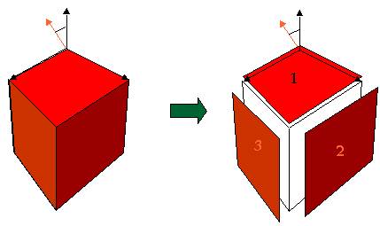
we can see that as a projection on the screen we have three polygons (1, 2 , and 3). By using the g.setColor() and g.fillPolygon() routines we can color the pixels of each polygon with a different shade of red. The direction of the incoming light will determine the amount of red to be used to fill the polygon. So we need two things:
a) A table of all shades of red to pick from
b) A way of determining the direction of the surface of each polygon (in world space) in order to find the angle with the light direction (the orange arrow). The bigger the angle between the surface and the light the more the shade of the red color.
In the next sections we will show how vectors will allow us to detect these angles in 3D space and how to produce a series of color table.
Vectors
Vectors are three-dimensional entities that show direction in space. Think of yourself as being at point (0,0,0) and looking at direction i, j, k. Or, in other words, a vector is a set of three numbers that tell us where to look at. We always assume that we are located at the origin (0,0,0).
So we define a vector as a class with three components:
public MyVector(double x, double y, double z){
i = x;
j = y;
k = z;
}
Notice that we use the i, j, k letters instead of x, y, z because a vector is different from a point even though it is defined in the same way. A vector shows a direction. A point shows a location.
Given two points in space we can create a vector by positioning it back to the (0,0,0) reference point:
public MyVector buildVector( point vert1, point vert2){
i = vert2.x-vert1.x;
j = vert2.y-vert1.y;
k = vert2.z-vert1.z;
return this;
}
Normalization
A normalized vector is a vector where each of its components is divided by the length of the vector:
public vector(double x, double y, double z,boolean normalized){
double t = Math.sqrt(x*x + y*y + z*z);
i = x/t;
j = y/t;
k = z/t;
}
The length of is the square root of the addition of the squares of the components.
Math.sqrt(x*x + y*y + z*z);
Normalization serves a purpose. As we mentioned earlier, vectors show direction. Their length should be insignificant when showing a direction. For example, if we are told to look one foot ahead, then one foot right, and then one foot up it is the same as being told to look five feet ahead, five feet right, and five feet up. We are still looking at the same direction. In the example below, after normalization, the two normalized vectors are the same length:
When we normalize we actually equalize the length of the two vectors. The normalization operations is:
public void norm(){
double t = Math.sqrt(i*i+j*j+k*k);
i = i/t;
j = j/t;
k = k/t;
}
Cross product
Cross product of two vectors is an operation that results in a vector perpendicular to the other two:
public void cross(vector v1){
temp.i = j*v1.k - k*v1.j;
temp.j = k*v1.i - i*v1.k;
temp.k = i*v1.j - j*v1.i;
i = temp.i;
j = temp.j;
k = temp.k;
}
The direction of the cross product can be determined by the order we select the operands. The corkscrew rule shows the direction of the cross product. In the above picture, if we choose the green and then the orange, the resulting red vector will be looking upwards. If we choose the orange first and then the green the red vector would be looking downwards.
Dot product
The dot product gives us the cosine of the angle between two vectors:
public double dot(vector v1){
return v1.i*i+v1.j*j+v1.k*k;
}
MyVector class
The following class MyVector defines a vector and its related operations:
public
class MyVector{
double i,j,k;
public MyVector(double x, double y, double
z){
i = x;
j = y;
k = z;
}
public MyVector(double x, double y, double
z,boolean normalized){
double t = Math.sqrt(x*x+y*y+z*z);
i = x/t;
j = y/t;
k = z/t;
}
public MyVector buildVector( MyPoint
vert1, MyPoint vert2){
i = vert2.x-vert1.x;
j = vert2.y-vert1.y;
k = vert2.z-vert1.z;
return this;
}
public double dot(MyVector v1){
return v1.i*i+v1.j*j+v1.k*k;
}
public void cross(MyVector v1){
MyVector temp = new
MyVector(0.,0.,0.);
temp.i = j*v1.k - k*v1.j;
temp.j = k*v1.i - i*v1.k;
temp.k = i*v1.j - j*v1.i;
i = temp.i;
j = temp.j;
k = temp.k;
}
public void norm(){
double t = Math.sqrt(i*i+j*j+k*k);
i = i/t;
j = j/t;
k = k/t;
}
public void print(){
System.out.println("i:" +
i);
System.out.println("j:" +
j);
System.out.println("k:" +
k);
}
}
Hint
For the purpose of this book:
1) Two vectors determine a plane in space. The cross product is a vector perpendicular to that plane.
2) The cross product is a vector that shows the direction of a plane. The light is a vector that shows the direction of the incoming light. The dot product gives us the angle between the two vectors, in other words the amount of light that falls on that plane.
Color Tables
In Java a color is defined with three numbers:
Color myColor = new Color(int red, int green, int blue);
Each number declares the amount of red, green, and blue that composes that color.
The following are different color declarations:
Color color = new Color(0,0,0) is black
Color color = new Color(255,255,255) is white
Color color = new Color(255,0,0) is red
Color color = new Color(0,255,0) is green
Color color = new Color(0,0,255) is blue
Array of shades
To paint the faces of a solid we need to have a palette of colors, or shades of a color. To do that we need an algorithm that will create an array of colors that are alteration of one basic color (i.e. red):
The algorithm is as follows:
void setColor(Color c) {
double r, g, b;
Color[] shadeTable;
r = c.getRed();
g = c.getGreen();
b = c.getBlue();
r /= 255.;
g /= 255.;
b /= 255.;
shadeTable = new Color[256];
for( int i = 0; i < 255; i++ )
shadeTable[i] = new Color((int)(r*i),(int)(g*i),(int)(b*i));
}
This algorithm will take a basic color and create 256 shades of that color and fill the shadeTable[] array of colors.
Notice that each basic color is associated with 256 other colors called shades. So when we define 10 colors to use for coloring our objects in a scene we actually allocate 10 x 256 = 2,560 colors. This may become a problem because different monitors can support only that many colors at the same time. Therefore, keep in mind that shade colors increase significantly depending on the number of colors and the number of shades.
Shade Calculation
At this point, we know how to create an array of color shades and how to represent direction of planes in 3D using vectors. What we will do is to determine which shade to choose from the colorShade[] array:
In the above illustration we show a red surface and we will determine the shade of red depending on the direction of the light.
First we declare a light vector:
MyVector vlight = new MyVector(-1, 1, 2);
Since we have three points in the faces object we can build two vectors out of 01 and 12 points. Then we take the cross product, normalize it, and find the dot product with the light.
The code for calculating the shade and returning back an integer number between 0 and 255 which is the array number where the shade color exists is a follows:
int calcShade(){
int shade;
temp1.buildVector( points[0], points[1] ).cross(
temp2.buildVector( points[1], points[2] ));
temp1.norm();
shade = (int)( 255*temp1.dot(vlight));
if (shade <= 0) shade = 0;
return shade;
}
First, we build two vectors, one from points [0] and [1] and the other from points [1] and [2]. We then cross product them to define the perpendicular vector temp1. We then normalize temp1 to give it a unit length. Then we dot product temp1 with the light vector vlight. The dot product will be a number between -1 and 1 (since it is a cosine). We multiply that number by 255 in order to scale it between -255 and 255. If it is negative means the vlight vector is under the surface and it not visible. If it is positive we return an integer number between 0 and 255 which is the array index for the shadeTable[].
An alteration of the line
shade = (int)( 255*temp1.dot(vlight));
can be:
shade = (int)( 100 + 155*temp1.dot(vlight));
This will assure that if the angle is 0 the shade table will still be at least 100. The variable shade will oscillate now between 100 and 255.
The result is: