The Mathematical Concept of the Third-dimension
If we look in the world around us we may notice that all objects exist in a three-dimensional space. Yet we all know that the eye, which is our way of seeing and conceiving the world, is an organ whose functionality is based on an almost two-dimensional surface. So that means that there must be a connection between two and three dimensions. The connection is that our understanding of a three-dimensional world is based not on its 3D nature per se (since computer screens are 2D) but on the behavior of 3D projections on the surface of our eye (or the screen). Lets take an example: the following object can be claimed to be either 2D or 3D yet on the surface of the eye it appears 2D. If however we rotate the object we can determine its true nature. But rotating still involves a 2D representation, that is, the projection on the surface of the eye. So the determination of the 3dimensionality of the object is based on the relationships of the shapes on the projection surface:
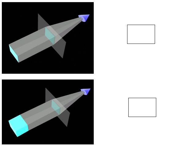
Figure An object is projected on the screen. The resulting projection (right) can be confusing or misleading about the shape, type, or volume of the 3D object (in this case a square panel as opposed to a cube)
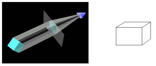
Figure. After a rotation in space the object is projected on the screen. The resulting projection (right) convinces the viewer more about the shape, type, and volume of the 3D object
In the above images, we can see that when rotated an object conveys more information about its 3D nature. In fact, the more movements we can allow the viewer to do the more understanding s/he would have of the space and the objects in the space. Unfortunately, we always have to work with projections because both computer screen and our eyes are flat projection surfaces. So we need to find a way of displaying the projection of 3D objects in such a way that the viewer will recognize them. To accomplish that we need to a) define the objects and b) project them. (Until we project them on the screen we will not know how they look). In the following sections we will show how to define 3D objects and how to project them using the existing Java objects we used in 2D.
Defining 3D objects
So far we have dealt with points, segments, and shapes using two variables to describe their geometry. These two variables we called x and y and we declared them as doubles. (the rationale of using double instead of int is based on the fact the measurements can be fractional, i.e. 3 feet and 2 inches, or 5.25 meters. We cast them into int only when we have to draw them on the screen because computer screen use pixels that are not fractional i.e we cannot say 2.6 pixels long. It is either 2 or 3 pixels long. )
In the case of the class MyPoint we used the following definition:
public class MyPoint {
double x, y; // data members
//*** Constructor
public MyPoint(double xinput, double yinput){
x = xinput;
y = yinput;
}
}
Now we can add one more double called z. That will automatically allow us to assign values that will define the dimension of height (or depth). The class will become:
public class MyPoint {
double x, y, z;
}
and the constructor of the MyPoint class will be:
public MyPoint(double xinput, double yinput, double zinput){
x = xinput;
y = yinput;
z = zinput;
}
Now we can adjust the standard transformation methods (move, scale, rotate).
Move and scale is simply adding the third dimension:
//**********************
public void move(double xoff, double yoff, double zoff){
x = x + xoff;
y = y + yoff;
z = z + zoff;
}
//*********************
public void scale(double xs, double ys, double zs){
x = x * xs;
y = y * ys;
z = z * zs;
}
Rotation involves three methods instead of one. The reason is that we can rotate in three directions in space (i.e. around the three axes). So we need to convert the 2D rotation method (that involved only x and y) into three methods for x-y, y-z, and z-x. As a reminder of the 2D rotation we display it below:
//**********************
public void rotate2D (double angle ){
double tempx = x * Math.cos(angle) + y * Math.sin(angle);
double tempy = y * Math.cos(angle) - x * Math.sin(angle);
x = tempx;
y = tempy;
}
In fact that remains the same, and it allows us to rotate around the z axis, where z is constant and only x and y is changing. The three rotation methods use the structure of rotate2D (above) except we create all possible combinations of x, y and z. The result is:
//********************** Rotation around the z-axis
public void rotatez(double angle ){
double tempx = x * Math.cos(angle) + y * Math.sin(angle);
double tempy = y * Math.cos(angle) - x * Math.sin(angle);
x = tempx;
y = tempy;
}
//********************** Rotation around the x-axis
public void rotatex(double angle ){
double tempy = y * Math.cos(angle) + z * Math.sin(angle);
double tempz = z * Math.cos(angle) - y * Math.sin(angle);
y = tempy;
z = tempz;
}
//********************** Rotation around the y-axis
public void rotatey(double angle ){
double tempx = x * Math.cos(angle) + z * Math.sin(angle);
double tempz = z * Math.cos(angle) - x * Math.sin(angle);
x = tempx;
z = tempz;
}
As you can see we have made all possible combinations of x, y and z using the generic rotation structure. Now where does the generic rotation structure come from? Simply by using the following trigonometric implementation:
Suppose that we want to rotate a point A (x, y) to position B (x’, y’) around a center O (0,0) by an angle b as shown in the following sketch:
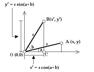
Now look at the triangle OBC. The sine of its a+b angle is y’/r and its cosine is x’/r. So that means:
x’ = r * cos(a+b) and
y’ = r * sin(a+b).
Now both expressions can be extended into:
x’ = r * cos(a+b) = r * cos(a) * cos(b) – r * sin(a) * sin(b)
y’ = r * sin(a+b) = r * sin(a) * cos(b) + r * cos(a) * sin(b)
But since x = r * cos(a) and y = r* sin(a) the above expression becomes:
x’ = r * cos(a) * cos(b) – r * sin(a) * sin(b) = x * cos(b) – y * sin(b)
y’ = r * sin(a) * cos(b) + r * cos(a) * sin(b) = y * cos(b) + x * sin(b)
The last part of the expression in Java looks like:
x’ = x * Math.cos(angle_b) – y * Math.sin(angle_b);
y’ = y * Math.cos(angle_b) + x * Math.sin(angle_b);
If we apply the same in the other directions we end up with the two other methods rotatex() and rotatey() shown earlier. The combinatorial logic of transformations has been studied extensively in an area of mathematic called linear algebra. Mathematicians there have produced “techniques” of creating all possible combinations of a structure given a set of parameters, such as in our case the rotational transformations. These “techniques” are called matrices and they represent a visual way for making sure that all possibilities are expressed. For example, the following matrix is used as:
which can be transformed into the set of equations:
x’ = sx * x + 0 * y + 0 * z + 0 * 1 = sx * x
y’ = 0 * x + sy * y + 0 * z + 0 * 1 = sy * y
z’ = 0 * x + 0 * y + sz * z + 0 * 1 = sz * z
1 = 0 * x + 0 * y + 0 * z + 1 * 1 = 1 * 1
For more on matrices please read chapter 11 of Haer and Baker “Computer Graphics” Second Edition (Prentice Hall).
Projecting on the Screen
After establishing the structure of a 3D point we need to create an object out of these points (let say a cube) and then project them on the screen to see them. First we create a class called MySpace and we define the points of a cube:
public class MySpace
extends Applet{
MyPoint[] points;
//**********************
public void init(){
points = new MyPoint[8];
points[0] = new MyPoint(0., 0., 0. );
points[1] = new MyPoint(100.,0., 0. );
points[2] = new MyPoint(100.,100.,0. );
points[3] = new MyPoint(0., 100.,0.
);
points[4] = new MyPoint(0., 0., 100.);
points[5] = new MyPoint(100.,0., 100.);
points[6] = new MyPoint(100.,100.,100.);
points[7] = new MyPoint(0., 100.,100.);
}
}
Then we need to draw these points using the g.drawString (“.”, xp, yp) as we did in the 2D version of this book. The problem is that we need two integer numbers xp and yp and we have (from the MyPoint structure) three double variables x, y, and z. This situation can be illustrated in the figure below:
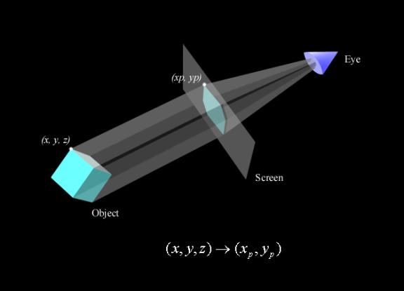
The answer is quite simple: we cast x and y into integers and we get rid of z. So the paint method would look like:
//*******************
public void
paint(Graphics g){
for(int i=0; i<8;
i++)
g.drawString("o", (int)points[i].x,
(int) points[i].y);
}
To rotate the points we simply need to use the mouse dragging movement to extract the angles of rotations that we pass to the rotatex and rotatey methods of the MyPoint class:
//*********************
public boolean
mouseDown(Event e, int x, int y){
xdown = x; // xdown is a global variable
ydown = y; // ydown is a global variable
return
true;
}
//*******************
public boolean
mouseDrag(Event e, int x, int y){
int xoff = x - xdown;
int yoff = y - ydown;
for(int i=0;
i<points.length; i++){
points[i].rotatey(xoff
* Math.PI/180.);
points[i].rotatex(yoff
* Math.PI/180.);
}
repaint();
xdown= x;
xdown= y;
return true;
}
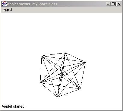
The result of this is:
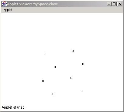
which is a rotate cube.
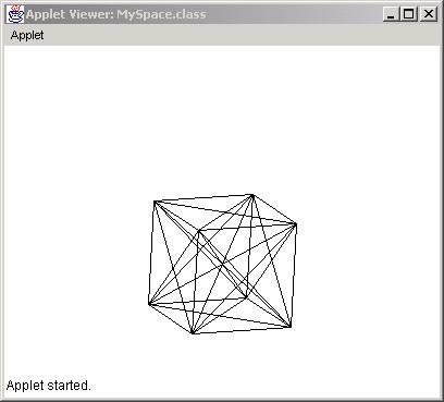
To visualize better the cube we can use lines that connect each point to all the other ones. This can be done by altering the paint method as follows:
//*******************
public void paint(Graphics g){
for(int j=0; j<8;
j++)
for(int i=0; i<8;
i++)
g.drawLine((int)points[i].x, (int)
points[i].y,
(int)points[j].x, (int) points[j].y );
}
The result is:
Orthographic/Perspective Projections (Theory)
The method of deriving the projection point xp and yp through the x, y and z coordinates is also referred to as “orthographic” projection. The rationale is pretty simple:
Let (x,y,z) be a point in space. In Java terms this point
should be a set of doubles as shown below:
double x,y,z;
Let xP and yP be the projection of the above (x,y,z) point
on the screen. In other words, xP and yP is the pixel location on the screen.
In Java terms this projection point is a pair of integer numbers as shown
below:
int xP, yP;
To project (x,y,z) on the screen we need to collapse this
point perpendicularly to the screen (that is, along the z-axis). In other words,
we need to make the z coordinate 0 (assuming that the screen is coinciding with
the xy plane) as shown in the diagram below.
In addition, the x and y coordinates need to be casted into
integer numbers. Therefore, the projection method may look like this:
xP = (int)
x ;
yP = (int)
y ;
Notice that the z coordinate does not play any role in the projection method. This means that no matter how far away the object gets from the screen, its projection will always be the same. In contrast, in perspective projection z does play a role in the projection method. According to the perspective formula shown below, x and y are related to z so that as the object moves along the z axis its projection changes.
double eye = 512.;
double t =
1.0/(1.0-((double) z / eye ));
xP = (int)( x * t);
yP = (int)( y * t);
The variable eye represents the distance of the viewer to
the screen of projection. The smaller that number the closer one gets to the
screen resulting in wide angle projection. The formula for the perspective
projection is produced as follows:
Let P(x,y,z) be a point in 3D space and P'(x',y') be its
projection on the screen. As P moves back and forth (or moves in general) so
does its projection P' on the screen. The parametric equation that connects the
P' with P as P moves is:
x' = x * (1 - u)
y' = y * (1 - u)
z' = (z + eye) * (1 - u)
where u can oscillate between 0 and 1. When u=0 then x' = x
and when u=1 x' = 0 (for x). Therefore x' oscillates between 0 and x. If we
solve the z part for u then u = z / z = eye (where eye is the distance of the
viewer to the screen). Plugging u into x' and y' equations results in the
formulas:
x' = x * (1 / 1 - z / eye)
y' = y * (1 / 1 - z /eye)
or
x' = x * t;
y' = y * t;
where t = 1 / 1 - z / eye
Orthographic/Perspective Projections (Implementation)
The Java implementation of the above formulas can be easily implemented in the existing MySpace and MyPoint classes in the following way. For the axonometric projection we need to define a method where we pass a MyPoint object and it returns a modified MyPoint with only the x and y variables affected. That is:
//*************
public MyPoint
setAxonometric(){
MyPoint p = new
MyPoint(0., 0., 0.);
p.x = x;
p.y = y;
return p;
}
and in the case of perspective we define a similar method:
//*************
public MyPoint
setPerspective(double distance){
MyPoint p = new
MyPoint(0., 0., 0.);
double t =
1.0/(1.0-((double)z/distance)); //Perspective
p.x = x * t;
p.y = y * t;
return p;
}
Both methods can me called for the main code (MySpace) within the paint() method in the following way:
for(int i=0; i<points.length; i++){
MyPoint p =
points[i].setAxonometric();
g.drawString(".",
(int)p.x, (int)p.y);
}
or
for(int i=0; i<points.length; i++){
MyPoint p =
points[i].setPerspective(512.);
g.drawString(".",
(int)p.x, (int)p.y);
}
The result for perspective projection look like this: