FormZ
1. General
FormZ
is a modeling and rendering program. The modeling part is called FormZ and the rendering part is called RenderZone (or RadioZity). Modeling is
the ability to build three-dimensional objects in a 3D geometrical space (see 3D Space) and
rendering is the simulation of a material world (with its textures, shades,
shadows, etc.).
FormZ
3.0 is the newest version. The previous
one was 2.9. They differ very little
mainly in the user interface layout and in a slight increase of new tools.
To
run formZ simply double-click on the formZ-Radiozity icon. You are presented
with the following screen:
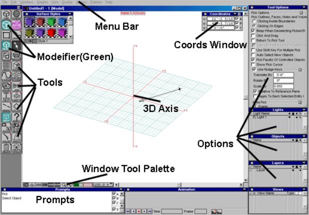
There
is:
·
a
menu bar at the top,
·
tool
icons on the left edge,
·
window
tool icons on the bottom,
·
floating
windows around (called options or
palettes) and
·
a
main window called [Model] with a 3D axes system.
Important
things to remember:
·
all
objects are created on the xy reference plane initially (the grid in the main
window). To change reference plane click on the leftmost icon on the bottom row
of commands
·
Floating
windows (if bothering) can be erased by clicking on the square on the top left
of each window. To retrieve them use the Windows menu item and then Palettes.
·
The
most important floating windows are the coordinates, which shows the xyz
location every time and the prompts window, which tells you what to do in every
step.
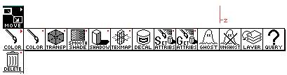
The
first three icons in the tools (left edge) are the creation icons. The first
two white icons define the various 2D shapes that can be created: rectangle,
polygon, circle, ellipse, polyline, curve, freehand line, and arc. Remember for the polyline that double-click will stop a sequence of
segments and triple-click will close
the polygon.
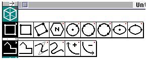
The
green icon specifies how the shapes will appear: as 2D shapes, as 2D
double-lined shapes, as a simple parallel extrusion (the height of which is
specified in the Heights menu item), as an extrusion to a point, or as a
wall-type extrusion.
![]()
Things
to remember:
·
Note
that there are white icons and green icons. The white icons are used to execute commands and the green to
specify how to execute them. For
example, the square icon creates a square sectioned object on the reference
plane and the green icon specify how the square will appear (2D, double lined,
extruded, extruded to a point, revolved, etc.)
·
Note
that most icons have a red dot on the top right of the icon. This means that
these icons have options associated
with them. For example, when you want to draw a polygon you need to specify the
number of points (pentagon, hexagon, etc.) To invoke those options remember to
press the Ctrl and Shift buttons on
the keyboard (or the option button for the Mac) and while you are pressing them
click on the icon. A dialogue window will appear with all the options.
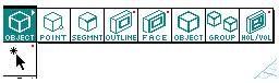
The
fifth (white) icon from the top is the picking icon. The green icon above it is
to specify what kind (or part) of object to pick: point, segment, outline (of a
shape), face, object, group of objects, and hole. Have in mind that all
commands can be applied any part of an object. That is, moving can occur to a
point, a segment, a face, a hole, and, of course, a solid object. Therefore,
always specify the type (or part) of an object before you modify it.
Notice:
·
To
select an object click on it. It will become red. Then select the next object,
and so on. You can also open a window (by draging the mouse) to pick all the
enclosed objects.
·
To
deselect (unpick) objects just click anywhere where there is no objects.
4. Creating openings (holes)
A
hole is the negative of an object and has its own identity as shown in the
picking selections. To create a hole you need a solid object. Follow the steps:
·
![]()
Press Ctrl-Shift (or
option-button on the Mac) and then click on the pick icon to invoke the picking
options. Select click inside boundaries to select a face.
·
Choose
the insert opening icon from the
first set of green icons
·
Choose
the shape of your opening (rectangle, circle, etc.)
·
Click
on the object's face where the hole will be placed.
·
Create
the hole.
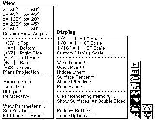
5. Displaying
objects and scenes
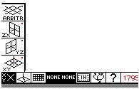
Use
the View menu bar to select
different angles of view. All commands are self-explanatory. Only notice that
the ones with and asterisk (*) can bring-up options when the Ctrl-Shift (or
Option) buttons are pressed.
Use the Display menu bar to select
different ways of rendering.
·
Wireframe is the fastest and displays
object as transparent objects.
·
Quick Paint displays objects as solids
with colors (fast but not accurate)
·
Hidden Line displays objects as solids
with lines (slow, great for black-and-white presentations)
·
Surface Render displays objects like Quick
Paint only is slower and very accurate
·
Shaded Render is a scanline type display
where object appear with colors and shades (slow but great for color
presentations)
·
RenderZone (when available) is the
slowest but most realistic display. Uses a technique called ray-tracing to
calculate the light intensities, reflections, ambient, specular light, shades,
shadows, etc. (the slowest)
·
Scenes
can be zoomed-in, -out and change angle by using the window tools palette
The
position, direction, and size of
objects can be altered through the geometric transformations: translation, rotation, and scaling:
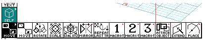
·
To
translate (move) an object, select
the translation icon (first one) then click on the object, and then move it. To
precisely move an object to a specific coordinate, simply type-in the
destination coordinates (in the prompts or the coords window). This applies to
all transformations.
·
To
rotate an object select the rotate
icon, then click on the object, then click on the reference plane to specify a
center of rotation, then drag the mouse (or type-in the angle of rotation) to
rotate.
·
To
scale an object select the scale
icon, then click on the object, then click on the reference plane to specify a
center of scaling, then drag the mouse (or type in the percentage of scaling)
to scale.
Notice:
·
You
can apply transformations on any kind
(or part) of an object. Therefore, a segment can be moved, a hole can be
rotated, or an group can be scaled. Just specify in advanced the type (or part)
of the object in the picking icons.
·
Also
movement can apply in parallel or perpendicular to the reference plane. When
the perpendicular icon ![]()
is selected (becomes
black) movement occurs perpendicular to the reference plane. This is an
important characteristic of the ambiguity of 3D space.
·
![]()
Always make sure that
you do not disturb the planarity of faces, and that you preserve the
compactness of 3D solids. If anything wrong happens use the triangulate command
(9th icon)
Copying
Transformations
can occur either as alterations of an object itself or by leaving traces
(copies). The copying icons specify the way those copies will occur.
![]()
·
Self will transform the object
itself.
·
Copy will leave one copy for
every transformation.
·
Repeat copy will leave a copy for every
transformation until a double-click on the mouse occurs.
·
Multi-copy will make a specified
number of copies (bring-up the options dialogue box to specify the number of copies).
The
derivation commands are used to derive new objects (usually from 2D - 3D or
from 3D - 2D). The derivation commands are:
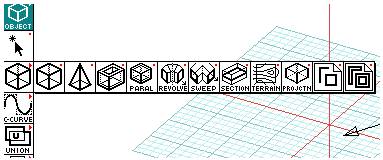
·
parallel derivation: pick any 2D shape. It will
be extruded in 3D (the height is in the heights menu)
·
convergence derivation: pick any 2D shape. It will
be extruded to a point in 3D (the height is in the heights menu)
·
derivative 3d enclosure: pick any 2D shape. It will
be extruded in a wall-type extraction in 3D (the height is in the heights menu)
·
parallel offsetting: pick any 2D or 3D object.
It will offset all the faces. (check the options)
·
revolution: pick any 2D shape. Pick an
axis. The 2D shape will be revolved into a 3d object around the specified axis
(check all the options with Ctrl-Shift for PC and Option for Mac buttons)
·
sweep: pick any 2D shape as the
section shape. pick any 2D shape as the path. The first shape (section) will be
swept along the other shape (path) creating a 3D object (a preview window will
appear).
·
Section: pick a 3D object (or a set
of objects). Then pick any 2D shape. The 3D object (or set of objects)) will be
sliced in two (check the options)
·
Terrain: pick a series of 2D
contour lines (in the order of height). Then pick a 2d shape (boundary of the
terrain). A 3D terrain model will appear (check the options)
·
Projection: Pick a 3D object (or set
of objects). It will project it on the active reference plane as a 2D shape.
·
2D derivation: Pick on any 3D object. It
will break all its faces down into 2D shapes (check the options).
·
2D enclosure derivation: Pick on any 3D object. It
will break all its faces down into 2D enclosure shapes (check the options).
Set operations
are used to separate, extract, and consolidate objects. The behavior of such
operations simulates the material world where objects are composed of mass. The
basics set operations are:
![]()
Union, intersection, and difference.
The split command produces the
result intersection and the two differences. Always click on two objects to
perform set operations. Objects should be enclosing some mass. Therefore, 2D
shapes, 2d enclosures, 3D solids, and 3D enclosures (wall-structures) are all
eligible candidates for set operations. If any of these objects does not behave
normally try fixing it with the triangulate
command (see above in transformations).
The
Join tool will treat two separate
objects as one so you can apply a set operation with a third object that
overlaps with the first two. Separate will separate the joined objects.
The
Group tool will allow you to select
(pick) a set of objects as one group. Extract and dismantle are related to
hierarchies of groups of objects. That is, if a group is part of another group
the extract will make the two groups
seprate and dismantle will cancel
all the groups.
Text
is simple. Click the Text icon and
then type in the text, size, font, etc. The text appears in 3D either as a
solid or as a 2D surface in space. Check the options by double clicking on the
text icon.
A FormZ Dummy Design Session
Setting up
·
Select
the desired units from the Working Units
in the Options menu
·
Select
Top from the Views menu (to work in
plan).
·
Select
1-16' scale (or whatever fits you)
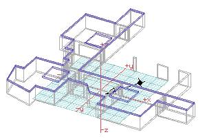
Creating the ground floor
wall structure
·
![]()
Select 10' from the Heights menu.
·
Select
the rectangle tools and the 3D enclosure modifier (![]()
and )
·
Draw
three squares.
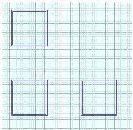
·
Draw
and modify all the modules of the plan.
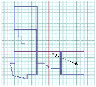
·
Select
Union.
·
Start
union-ing one by one all modules (make one big wall structure)
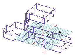
·
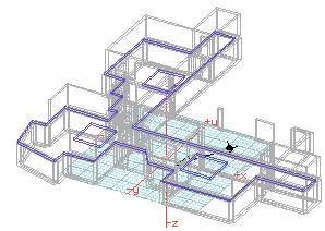
Select
a 30-60 view from the Views menu
Saving the file
·
Go
to File menu and select Save
·
Give
the file a meaningful name
·
Save
it as a .fmz file
Inserting openings/holes
·
Select
face from the picking modifiers![]()
·
Select
Insert Hole from the creation modifiers![]()
·
Select
a negative height (-4'-0")
·
Click
on the pick tool ![]()
while holding the Ctrl
and Shift keys (Option key if Mac)
·
On
the dialogue box click on the Inside Boundaries option.
·
Exit
the dialogue box
·
Select
the rectangle tool.
·
Click
on a face and drag the mouse to create the hole (note that the rectangle can
exceed the boundaries of the face)
·
Do
the same for all the holes (opening, doors, and windows) in the building
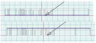
Save the file
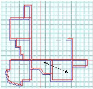
Creating the ground floor
ceiling
·
Change
you view to Top
·
Select
the parallel extrusion modifier![]()
·
Select
the polyline tool![]()
.
·
Select
a 1' height.
·
Trace
the boundaries of the building
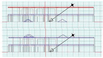
·
Change
you view to Front
·
Select
object from the pick modifiers
·
Pick
the ceiling object
·
select
the move tool
·
Move
the ceiling object to the top of the wall structure.
Save the file
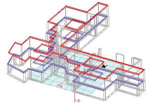
Ghosting the new objects
·
Select
Ghost from the attribute menu.
·
Select
all the objects you want to ghost (they will be visible but not pickable)
·
(To
unghost them select the Unghost icon and pick the objects to unghost)
Save the file
Creating the first floor
·
Change
your view to Top (plan)
·
Unghost
the ground floor
·
Pick
the ground floor (makes it active, shown in red)
·
Select
Duplicate from the edit menu (makes a copy of the active object)
·
Change
your view to Front (elevation)
·
Move
the first floor on top of the ground floor.
Save the file
Do the same for the ceiling
of the first floor.
Save the file
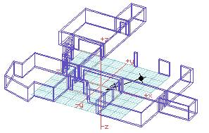
Adding pitched skylights
·
Change
your view to Top
·
Select
the convergence extrusion from the creation modifiers![]()
·
Select
the height to be 4'-0"
·
Select
the rectangle tool![]()
·
Draw
the three pitched roofs
·
Change
your view to Front
·
Move
the objects to the proper height
Save the file
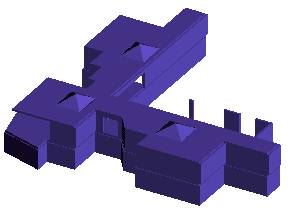
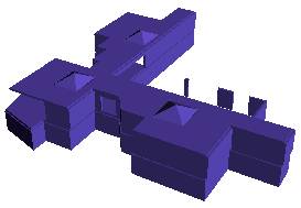
Creating a presentation
·
Choose
a view that shows the whole building (30-60 for example)
·
Select
Render Shaded for the Display menu to preview the building rendering
·
If
happy go to Underlay in the edit menu
·
A
dialogue box will appear
·
Choose
Show Underlay
·
Then
select a file (sky, clouds) or some other background file
·
(For
a Mac you need a TIFF or PICT file
·
For
a PC you need a .tif or .tga file
·
Check
the notes on photoshop to handle
that)
·
Get
out of the dialogue
·
Select
RenderZone for the Display menu
·
Save
the file as a tif or pict view (it is in the save as.. in the file menu)
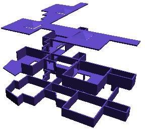
Creating an exploded
perspective
·
Change
the view to Front
·
Move
the objects to be exploded (in this case the floors) in different heights
·
Select
a 30-60 viewing angle
·
Select
Perspective from the View menu
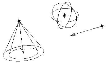
Lights
Lights are define by clicking on
the title of the lights palette:
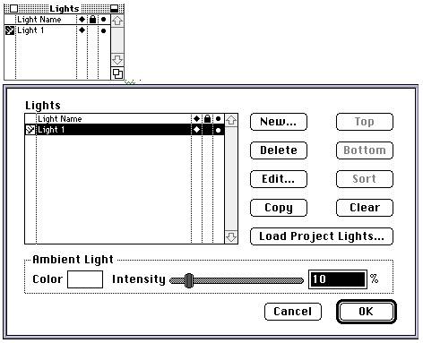
. . .
By
clicking New.. the following window appears:
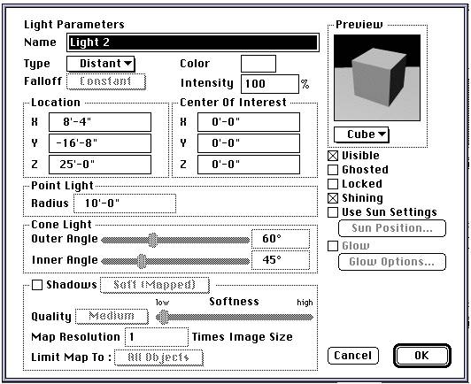
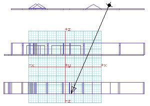
A
light has a name and can be Distant (parallel
rays), cone (spot lights) or point. It can have a color, intensity, radius or angle, and may or may not cast shadows. The shadow option should be on
only if shadows are visible and important because their calculations are
intense and can cause time delays. Ray
traced shadows are the most difficult so try using soft (Mapped) shadows instead. Lights can be moved (like objects)
using the Move tool.
Advanced Rendering: Tree
creation in formZ
Step 1:
Find
an image of a tree. Open it in photoshop. Clear up the background so it
is all the same color. Select the background (either with the magic wand or
with the color range). Invert the selection to select the tree.
![]()
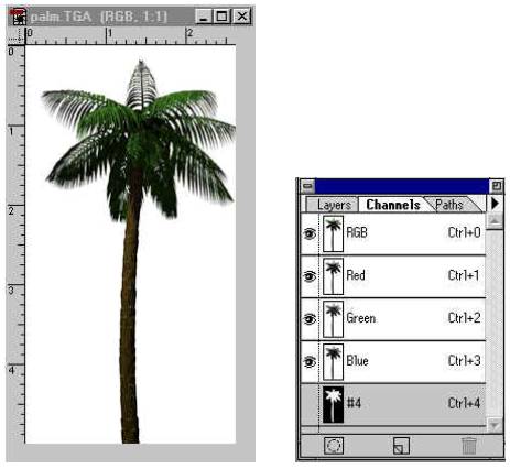
Step 2:
Open
the channels palette and select the make mask. You will
see a new channel with all the background in black. Black
means that those pixels will be transparent.
Save
the image as .tga or .tif. (In the
case of VRML save an additional file as gif98. The process is described in the
next section)
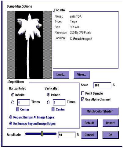
Step 3:
Open
formZ. Create a new material. In the material dialog select imagemap
and in the options load the .tga (or .tif) file. In the transparency
dialog select imagemap, then load the .tga file and
select alpha channel. You should be seeing a white tree with a black
background.
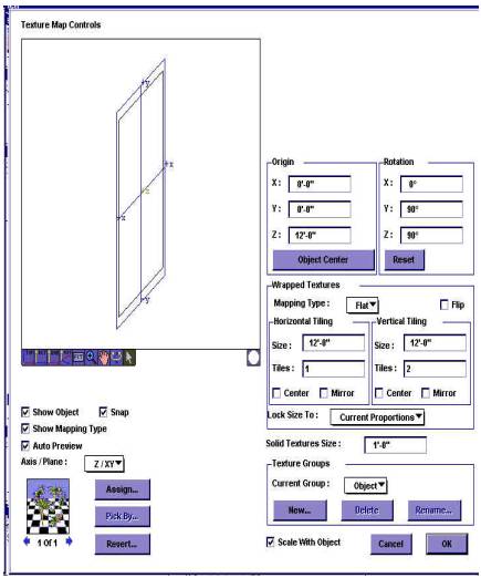
Step 4:
Select
the YZ plane and create a panel the size of the tree with its base
symmetrically over the 0,0,0 point. Select the tree material, choose the
texture map tool and click on the tree panel. You will be presented with
a textmap dialog (see figure below). Select mapping to be flat. Select y rotation
to 90 and x rotation to 90 (this will orient the image parallel to the
panel). Select current proportion. Select center on both directions
and set the tile number to 1 for the vertical direction.
Exit the dialog.
Make
a copy of the panel rotated 90 degree around the 0,0,0 so the
two panels are crossed at their center line.
Step 5:
Select
the “create symbol” tool. Select both panel in the scene. Click anywhere.
You will be asked to load a new library. Load a
new one and give names to both the library and the tree.
Done.
Any
time you want to place a symbol just click on the scene.